Wednesday 7 August 2013

Bugatti Veyron
My 2nd automobile model in CATIA. Took 2 days to model (16 hours straight streak).
The Bugatti Veyron EB 16.4 is a mid-engined grand touring car,
designed and developed by the Volkswagen Group and manufactured in
Molsheim, France by Bugatti Automobiles S.A.S.
The Super Sport version of the Veyron is the fastest street-legal
production car in the world, with a top speed of 431.072 km/h (267.856
mph). The original version has a top speed of 408.47 km/h (253.81 mph).
It was named Car of the Decade (2000–2009) by the BBC television
programme Top Gear. The standard Veyron won Top Gear's Best Car Driven
All Year award in 2005.

BMW i8 Vision Efficient Dynamics
BMW i8 Concept model in CATIA by me. Took me straight four days about 60 hours to model this.
The Vision Efficient Dynamics concept car is a plug-in hybrid with a three cylinder turbodiesel engine. Additionally, there are two electric motors with 139 horsepower. It allows an acceleration to 100 km/h (62 mph) in 4.8 seconds and an electronically limited top speed of 250 km/h (160 mph).
According to BMW, the average fuel consumption in the EU test cycle (KV01) is 3.76 litres/100 kilometers, (75.1 mpg imp), and has a carbon dioxide emission rating of 99 grams per kilometer (1,3 l/100 km and 33g CO2/km ; EU-PHEV ECE-R101). The estimated all-electric range is 50 km (31 mi), and the 24-litre diesel tank extends the total vehicle range to up to 700 km (430 mi). The lightweight chassis is made mainly from aluminium. The windshield, top, doors and fenders are made from polycarbonate glass, with the body having a drag coefficient of 0.22.

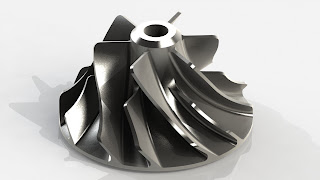
Turbine Rotor
A
turbine is a rotary mechanical device that extracts energy from a fluid
flow and converts it into useful work. A turbine is a turbomachine with
at least one moving part called a rotor assembly, which is a shaft or
drum with blades attached. Moving fluid acts on the blades so that they
move and impart rotational energy to the rotor. Early turbine examples
are windmills and water wheels. Rotor is the rotating part, and the
stator is the stationary part of the machine.

Torsen Differential
The
Torsen differential works just like a conventional differential but
can lock up if a torque imbalance occurs, the maximum ratio of torque
imbalance being defined by the Torque Bias Ratio (TBR). When a Torsen
has a 3:1 TBR, that means that one side of the differential can handle
up to 75% while the other side would have to only handle 25% of applied
torque. During acceleration under asymmetric traction conditions, so
long as the higher traction side can handle the higher percentage of
applied torque, no relative wheelspin will occur. When the traction
difference exceeds the TBR, the slower output side of the differential
receives the tractive torque of the faster wheel multiplied by the TBR;
any extra torque remaining from applied torque contributes to the
angular acceleration of the faster output side of the differential.
Torsen
differentials are used in many of the various Audi Quattro models,
excluding the A3 & S3 and TT (which have transverse-mounted engines
and use Haldex Traction 4WD systems).


Epicyclic differential 3D Model/Simulation
An
epicyclic differential uses epicyclic gearing to split and apportion
torque asymmetrically between the front and rear axles. An epicyclic
differential is at the heart of the Toyota Prius automotive drive
train, where it interconnects the engine, motor-generators, and the
drive wheels (which have a second differential for splitting torque as
usual). It has the advantage of being relatively compact along the
length of its axis (that is, the sun gear shaft).
Epicyclic
gears are also called planetary gears because the axes of the planet
gears revolve around the common axis of the sun and ring gears that
they mesh with and roll between. In the image, the yellow shaft carries
the sun gear which is almost hidden. The blue gears are called planet
gears and the pink gear is the ring gear or annulus.

Here is Video Tutorial for SolidWorks


Centrifugal Turbine Impeller 2D Drawings/3D Model/Video Tutorial
This
model is actually was part of work of my friend. He was having problem
reading the drawing file so he asked me if I could help me making this
part. At start I was thinking where to start but it was fun modeling
this little part as help for my friend. This is actually part of Steam
turbine assembly. This part is totally accurate.


Here is Video tutorial


Monday 5 August 2013
Axial Vector Engine
A
swashplate is rigidly fixed to the CAMDisk, and goes round with it as a
unit. Therefore the connecting rods are not fixed to the plate in any
way, but push on it with rollers or slipper pads that can glide over the
surface of the plate as it turns. The main point of attraction is the
use of CAM-Disk in place of Crank shaft to provide reciprocation. Since
the Engine is double Reciprocatory with corresponding strokes at both
sides, there is no unbalancing of masses i.e. full balanced. Battery
Ignition System is used with a spark plug for each cylinder. There are
one inlet and one exhaust for each cylinder. Fins thickness is not
calculated but 5mm is more than enough. Fuel Type used is Gasoline and
the engine can found application in Aerospace as well as Automotive.
Engine is mainly a torque converter type rather than speeder.
Specs:-
Cylinders =12 (6 both sides)
Bore Dia = 80mm
Stroke length = 110mm
Engine Type = Axial Vector Type 4 Stroke
Crank Mechanism = CAM Disk Mechanism
Engine Capacity = 26500cc/1618ci
This model is also winner for CADD Centre Training Services Facebook project contest with more than 1000 votes and stood first in more than 590 entries. Also this is my favorite model.
Connecting Rod of Gasoline Engine
Connecting Rod is the
connection between the piston and crankshaft. It joins the wrist pin of
the piston with the throw or crankpin of the crankshaft. For a given
size engine, lighter the connecting rod and piston the greater the
resulting power, and lesser the vibration as a result of the decreased
reciprocating weight. The connecting rod is split to permit its being
clamped round the crankshaft.
This model was part of my Advanced CAD/CAM lab assignment. Had fun modeling it. There is a funny incident related to it. I was unable to read the distance between the lower split of the connecting rod circular part with the upper circular part. Whole night I tried to understand and finally slept without getting the problem solved. That night I solved this problem in my dream and when I woke up I had the solution. So rather than preparing for college I took 24 minutes to model this drawing.
Had very fun modeling it.

Saturday 3 August 2013
Cam Follower Mechanism Drawings & Video Tutorial
Here is the 2D Drawing for the CAM Follower Mechanism we had drawn. The whole assembly is drawn & animated in SolidWorks. For Video tutorial you can visit our Youtube links.

Sunday 23 June 2013
Video Tutorial on Modeling Lamborghini Gallardo in CATIA v5

For the Tutorial on Modeling this Lamborghini Gallardo please goto my Youtube Channel
Here are the blueprints that I used. Please save them to your local disk and don't change their location once you insert them into Sketch Tracer.


Subscribe to:
Posts (Atom)