Thursday 25 April 2019

ISO 4762 M8 Screw/Bolt and Nut Metric Profile thread and Assembly Modeling

ISO Standards are very important in Mechanical Industry. So to explain how to use design data books and and how to use ISO standards, I have created these video tutorials. In these video tutorials, I have explained how to create ISO metric profile thread in SolidWorks and how to mate them.

I have used PSG Design data book from PSG College Coimbatore. This is one of the best book available and complete in all aspects. 


ISO Metric Thread Profile


ISO 4762 Screw Standard
Source :- PSG Design data book Page 5.61


Video Tutorials

English Version of ISO Bolt/Screw 

English Version of ISO Nut

Hindi Version of ISO Bolt/Screw-Nut assembly 

CATIA Modeling Tutorial


Saturday 20 April 2019

Four Jaw Chuck Assembly SolidWorks Video Tutorial

In this video tutorial we will be modeling a Four Jaw chuck based on 2D assembly drawing. In this video I will explain how to approach such drawings and reading all the dimensions. This is a full length video in which every single concept, basics and tricks will be covered related to Assembly Modeling.

A lathe chuck is used to hold bar stock, to be machined. It is mounted on the head-stock spindle of the lathe. To accommodate different sizes of bar stock, its jaws are required to be adjustable. All the jaws can be adjusted simultaneously, as in the case of a self-centering chuck, by manipulating it from one point, or each jaw may be adjustable independently. The jaws in this design are adjusted by manipulating a screwed pair. The jaws should be so adjusted that the bar stock, held in the chuck, is properly centered and rotates as desired.
You can download 3d model from here :- https://grabcad.com/library/4-four-jaw-chuck-1


Sunday 14 April 2019

Involute Teeth Profile Spur Gear Design

The involute profile is most common used in Gear designed and is generated from base circle. There are many ways to create gear and many times we ignore the standard construction method to save time. This should be avoided. So I have created this model which is equation driven.

That means we only need 4 parameters to define the whole spur gear design.
1. Number of Teeths
2. Module
3. Pressure Angle (usually 20ยบ)
4. Face Width

Design Calculations for Spur Gear

For Calculations I have used SMath Studio. It is a free Mathematical Notebook MathCAD software. You can download it for free from their official website https://en.smath.com/view/SMathStudio/summary.

In this video tutorial we will learn to model equation driven Spur gear using base circle as basis of construction. I will explain how to model the gear.

Many parameters are used and driven by only Teeth, Pressure Angle and Module.


For video Tutorial in SolidWorks:- https://youtu.be/TAQvypaPcTA
For video Tutorial in CATIA:- https://youtu.be/lMvuTouOM_g
For downloading 3d model CATIA:- https://grabcad.com/library/spur-gear-involute-profile-with-video-tutorial-1

Saturday 13 April 2019

Fuel Injection Nozzle with Full Length Video tutorial

In this video tutorial we will be modeling a Fuel Injection Nozzle or Atomiser based on 2d assembly drawing. In this video I will explain how to approach such drawings and reading all the dimensions. This is a full length video in which every single concept, basics and tricks will be covered related to Assembly Modeling.

The purpose of the fuel injector, atomizer or nozzle, as it is called, is to atomize or break the fuel into fine particles and to direct the spray into the combustion chamber so that every fuel particle mixes with the air compressed in the cylinder. In order to achieve this, injection takes place through very fine holes in the nozzle body at a pressure of about 160kg/cm^2.

The only tricky part of modeling is some missing dimensions and assuming them. If you want model or 2d drawing let me know in comment section or message us on our facebook page. This model is CFD ready. You can use this model for CFD simulation of Fuel injection nozzle. I know many of you use Flow simulations and need more models like this. 


For Video Tutorial :- 
1. Main Body
2. Other Parts of Assembly
3. Assembling all parts

Join our:-
Facebook Page :- https://www.facebook.com/MechanicalMachineDesign
Instagram :- instagram.com/mechanicalmachinedesign
Whatsapp :- https://chat.whatsapp.com/HrMvr1E5e3j3RH7Gl5oxyX
Discord :- https://discord.gg/7jMDy2
Telegram :- t.me/MechanicalMachineDesign

Wednesday 10 April 2019

Steam Stop Valve Assembly Drawing Full Length Video Tutorial with Expert guidance

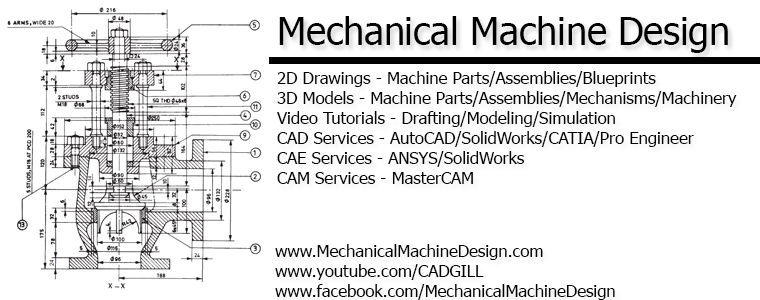
This drawing was one of the most complex drawings in P.S.Gill Drawing book. There were times during my engineering course when I started this drawing and failed to complete it as I lacked the workshop/toolroom experience which is a must to completely understand this drawing.

As always P.S.Gill have removed some dimensioned intentionally so we will need to use whole assembly dimensions in order to fully design this part. There was a note written below the drawing which said, 
"Assume, proportionately, any dimension missing". 
To assume these dimension, we need some expertise with such Drawings and some workshop/toolroom experience. As I mentioned earlier that I lacked that experience before, now I had enough experience to completely read all the dimensions in between the dimensions to completely draw it.
I have assumed dimensions too, but keeping proportions and other dimensions in mind. We can't assume any dimension randomly. I had used top-down and bottom-up design approach simultaneously to ensure Everything is completely defined. Finally, I have also created a video tutorial for the same in which I have explained the modeling procedure, reading drawing and all other steps necessary. This video is a bit long 153 minutes(2 hour 33 minutes, i lost track of time ๐Ÿ˜…) but it covers nearly everything related to this assembly. I watched some other video Tutorials also, but everyone had made some mistakes or missed out some Details. I am sure your drawing reading skills will increase by a big level after you have completed this assembly drawing after watching this video tutorial.

If you need the SW file or the 2D  you can download it from here. If you still had any problem regarding this assembly, you can message in the WhatsApp, Facebook, Telegram group or even comment here. Thanks for giving your precious time to read my post.

Video Tutorial :- https://youtu.be/WgaqCeYHvuA 


Thursday 4 April 2019

Wrapping Wire on helical spring video tutorial


As you can see on the above image. I have wrapped a 2mm wire on 5mm dia helical spring. This looks a little confusing to understand but there is a trick to it. Also SW has a limit of 100 number of revolutions but we created a 200 revolution spring around the helical spring.

The trick is very simple. I remember using this to create rectangular springs, triangular springs etc.

For Video Tutorial :- 

Wednesday 3 April 2019

Steam Stop Valve Drawing


Steam Stop Valve drawing for practice. A steam stop valve is mounted on the steam pipe, close to the engine to regulate the flow of steam through pipes and shut-off completely when not required. It is operated by means of a hand wheel. These valves have a low lift and hence can be closed and opened quickly.

This is one of the complex drawing in P.S.Gill Machine Drawing book Page-585 Fig (24.16). During my college time it looked like a horror movie since many dimensions were missing. Mr. P.S.Gill whose book I am using for 9 years has something special. He always removes or don't add some dimensions intentionally. This makes drawing these difficult. It took me some 3 hour to completely draw this 3D model in SolidWorks. I looked on internet and everyone has designed this assembly wrong. Someone misplaced bush or someone misplaced bush. But finally I completed it in SolidWorks.

This model can be used for Thermal steam flow simulation and is ready for this. If you need the file just let me know.

If you having any problem understanding the drawing or reading any dimension, let me know. 


Tuesday 2 April 2019

Automotive Carburetor Body Drawing

Various component parts of a carburetor are either housed in or mounted on a main component called the carburetor body. It is usually made of aluminium. In this video tutorial we will be designing an Automotive Carburetor Body in SolidWorks. The drawing used is from Machine Drawing by P.S.Gill Fig 28.10. It was not very difficult to model, but the main focus here is how to order feature tree.


I have attached the 2D drawing here. 

For Video Tutorial

Monday 1 April 2019

Brain Gear Mechanism Modeling & Simulation in SolidWorks Video Tutorial

Brain Gear mechanism in SolidWorks Video Tutorial


This is Part 11 of Mechanism Video Tutorial Series in SolidWorks. In this video tutorial we will learn how to model & simulate Brain gear mechanism in Solidworks. This is a specific type of model which is mainly used by 3D printing companies to show the capability to manufacture internally assembled components. Brain gear doesn't have any importance mechanically but you should have sound knowledge about gears (specially bevel) to model this. There are many people who never wanted to share the knowledge behind the modeling and working of brain gear, but here i am sharing everything related to this.

If you liked this video please give this video a like and subscribe to our channel for more exciting updates in future. 

Our Facebook page :- https://www.facebook.com/MechanicalMachineDesign
Our Facebook group :- https://www.facebook.com/groups/824188254599835

To download the part file please click on this link https://drive.google.com/open?id=1uPFXqFQJ4XliGHgry1aLcmGLPzKw9n1_

For video tutorial :- https://www.youtube.com/watch?v=FItakcTnMlc


Join our:- 

Facebook Page :- https://www.facebook.com/MechanicalMachineDesign
Instagram :- instagram.com/mechanicalmachinedesign
Whatsapp :- https://chat.whatsapp.com/HrMvr1E5e3j3RH7Gl5oxyX
Discord :- https://discord.gg/7jMDy2
Telegram :- t.me/MechanicalMachineDesign